Three geometric tasks
- Lattice tiles: derive branch directions from a space-filling cell, give them material thickness, and connect repeated tiles.
- Boundary fitting: adapt micro-elements to an object, verify containment, and bridge gaps between retained elements.
- Printing supports: cover the selected support zone with contact tips, then coarsen the interior while preserving those contacts.
01 / Choose a cell, then construct its dual
A repeatable lattice needs compatible cell interfaces. This construction derives branches from a space-filling polyhedron and turns them into parametric solid tiles. The examples below show the dual directions and their connection across cells.
A lattice tile does not have to begin with a cube. Space-filling polyhedra provide a systematic source of cell geometries. Their dual graphs describe directions along which a parametric tile can extend, while the polyhedral cell defines where neighboring copies meet.
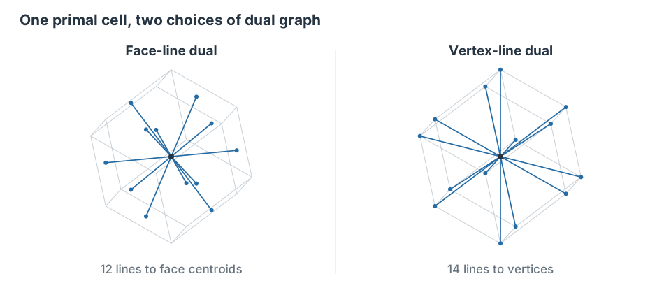
A face-line dual joins the cell centroid to each face centroid. A vertex-line dual instead joins it to each vertex. The two choices produce different tile families and different interfaces in the resulting lattice.
The primal cell supplies more than a visual outline. Its faces and vertices determine the incidence relations from which the dual is constructed, and its ability to fill space supplies a repeatable arrangement of neighbors. Selecting a different space-filling polyhedron changes those relations and creates another source of lattice topology.
In the face-line construction, the branch associated with a face reaches the interface shared with a neighboring cell. That correspondence gives a direct way to reason about how adjacent copies connect. The vertex-line construction chooses another set of directions and must be interpreted with its own arrangement of neighboring cells; it is a distinct construction rather than a recoloring of the face-line tile.
Other space-filling cells
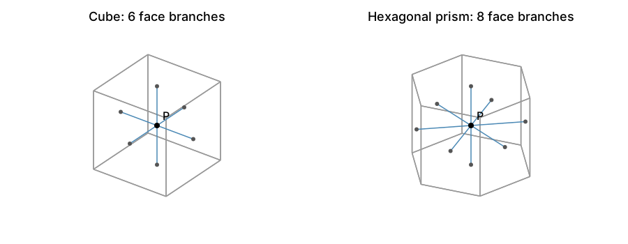
The same face-line rule applies to other space-filling polyhedra. A cube has six square faces and therefore six branches. A hexagonal prism has two hexagonal end faces and six rectangular side faces, giving eight branches. In each case P is the cell centroid and each branch ends at a face centroid. These regular examples make the change in branch directions and connectivity explicit.
02 / Turn a graph into a parametric lattice
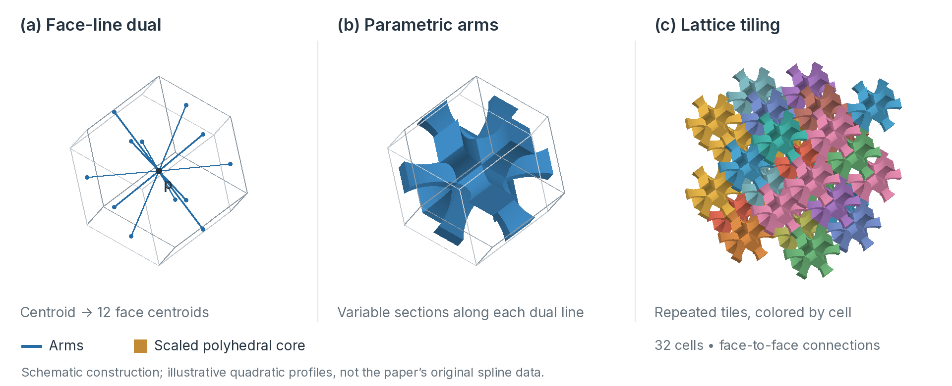
- Construct the coreScale the primal polyhedron about its centroid to obtain a central joint.
- Sweep the armsUse variable cross-sections along the dual directions. The profile controls the material around each branch.
- Repeat across cell interfacesMatching terminal sections meet across shared cell faces. In this example the renderer verifies the 108 neighboring face interfaces.
The paper develops parametric constructions compatible with boundary-representation workflows, classifies the resulting topologies, and studies printed examples and mechanical behavior. The illustration above explains the construction; it is not a finite-element result.
A line graph alone has no material thickness. The parametric construction turns its branches and central joint into volumetric elements, making cross-section size and variation explicit design parameters. The shrinking factor of the core and the profiles of the arms affect how material is distributed between the center and the interfaces.
Matching two terminal sections establishes positional connection across an interface. Higher-order smoothness requires additional control of the profiles and their derivatives; it does not follow just from placing two cells next to one another. The paper discusses these design choices in its trivariate construction. The colored assembly here illustrates matching interfaces without claiming to reproduce those exact control points.
03 / Fit a microstructure inside a particular object
An interior structure must fit the object as well as connect to itself. A volumetric cage guides the micro-elements; containment tests protect the boundary, and bridging elements restore missing connections.
Periodic tiling answers how cells repeat. Filling an arbitrary object asks an additional question: how should the structure follow the object’s geometry while staying inside its boundary?
- Build a volumetric cageThe cage acts as a trivariate map that guides the placement and deformation of micro-elements.
- Synthesize and verify elementsGenerate candidate elements in the cage, then retain those verified to lie inside the polygonal or trimmed-spline boundary representation.
- Bridge gaps in connectivityAdd bridging elements where the retained structure would otherwise be disconnected.
Individual elements can vary in geometry and potentially in material composition. This provides a way to design the interior, rather than merely clipping an unchanging periodic pattern at the object boundary.
The cage is a geometric map from a parameter domain into the region around the object. Applying that map to the micro-elements changes their position and shape together, so the generated structure can follow a prescribed interior organization. It also means that a tile that was regular in parameter space may be stretched or compressed in physical space.
Containment and connectivity must then be considered separately. Rejecting elements that do not lie inside the boundary protects the exterior shape, but can leave gaps between retained elements. Bridging elements address that second problem. The method is therefore a sequence of geometric construction, verification and connection, rather than a single clipping operation.
04 / Define the support zone and its contact coverage
A printing support must reach the selected model surface without unnecessary interior detail. The method controls contact coverage and tip geometry, then merges eligible interior tiles while preserving the model contacts.
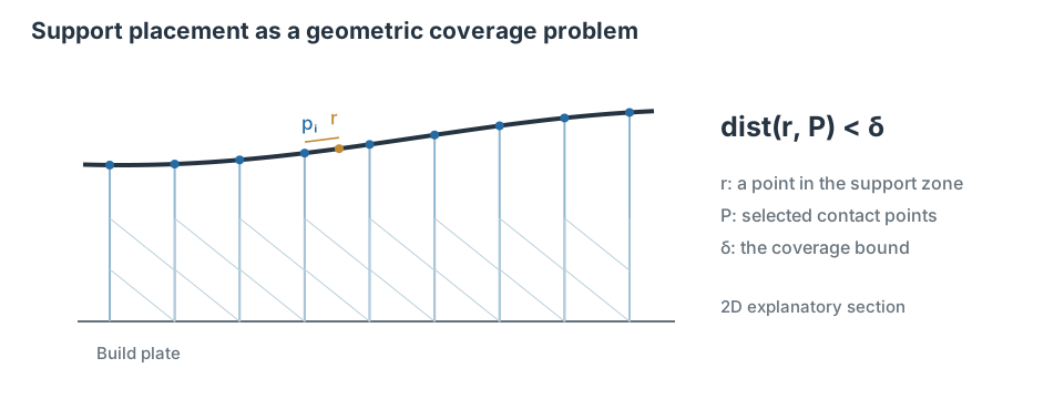
Multiresolution lattice support connects geometry to fabrication constraints. The user can specify which slopes require support, choose tile dimensions and sizes, and control coverage of the support zone by contact points. The method also allows analysis to guide optimization.
A support structure must both reach the parts of the model that need support and carry those contacts through a printable structure. The method separates the contact problem near the model from the arrangement of lattice tiles farther away. This separation becomes important when reducing the amount of fine-resolution structure.
Let Z be the selected support zone on the model and P the set of contact locations. The coverage objective is that every point r in Z has a contact within a prescribed distance δ. This is a geometric condition on the distribution of contacts, distinct from a mechanical condition on the strength of the material between them.
The base tile size governs the spacing of the locations from which tips can be generated. In the regular arrangement described in the paper, successful tips and the permitted surface slopes relate this spacing to the distance between contacts on the model. This relationship has assumptions: missed rays, rejected tips or changes to the contact-search rule cannot simply be ignored when interpreting coverage.
The printing direction and a user-selected slope threshold determine which surface orientations require support. The initial support volume comes from the model’s bounding box, optionally expanded to leave room for the lattice. Tile width, length and height are chosen together with the allowed slopes of the diagonal arms, so the desired support resolution must also be compatible with the printer geometry.
05 / Construct and verify the contact tips
The support lattice uses parametric tiles with diagonal arms, rather than the face-line tile shown earlier in this page. A tile typically provides four upward and four downward arms, with variants for wider bed contact, modified arm slopes or thicknesses, and an additional central vertical pillar. These features give the support algorithm attachment locations and ways to connect different resolutions.
Before tips are created, the algorithm classifies the tile boxes against the model using an AABB-based bounding volume hierarchy. Tiles whose boxes are inside or intersect the model are removed. Remaining tiles with no neighbor directly above are marked as top tiles; those with no neighbor directly below are bottom tiles. A tile can belong to both groups, which matters for support inside a gap.
Find a contact by ray intersection
From a point on a relevant arm face, the method first casts a nearly vertical ray slanted slightly inward to distribute contact positions more evenly. If that attempt fails, it tries a vertical ray. Top tiles cast upward and bottom tiles downward. The BVH narrows the search, but an actual model intersection is still needed; when several intersections are found, the nearest one is retained.
At the hit point, the surface normal is checked against the requested slope condition. For an accepted contact, a swept tip connects the arm to the model. The tip end is oriented along the surface normal, and its length and diameter are controlled by the design parameters. Tip lengths and orientations can therefore differ even for arms of the same tile.
Reject interference and unnecessary structure
A candidate tip is rejected if it exceeds the permitted length or interferes with another tip, a tile or the model. Arms that contribute no support can be removed, but an arm shared with a neighboring arm may be retained for structural connectivity. Tiles that lose all relevant supporting arms are filtered, with the classification and removal propagated where appropriate.
These checks explain why an overhang-angle test alone is not a complete support algorithm. A surface location may require support, yet a particular arm may fail to reach it, generate an excessively long tip, or collide with surrounding geometry. The paper discusses difficult cases and possible alternatives to the ray-based contact search; those alternatives must also be checked against the contact-spacing objective.
06 / Coarsen the interior without removing contact tips
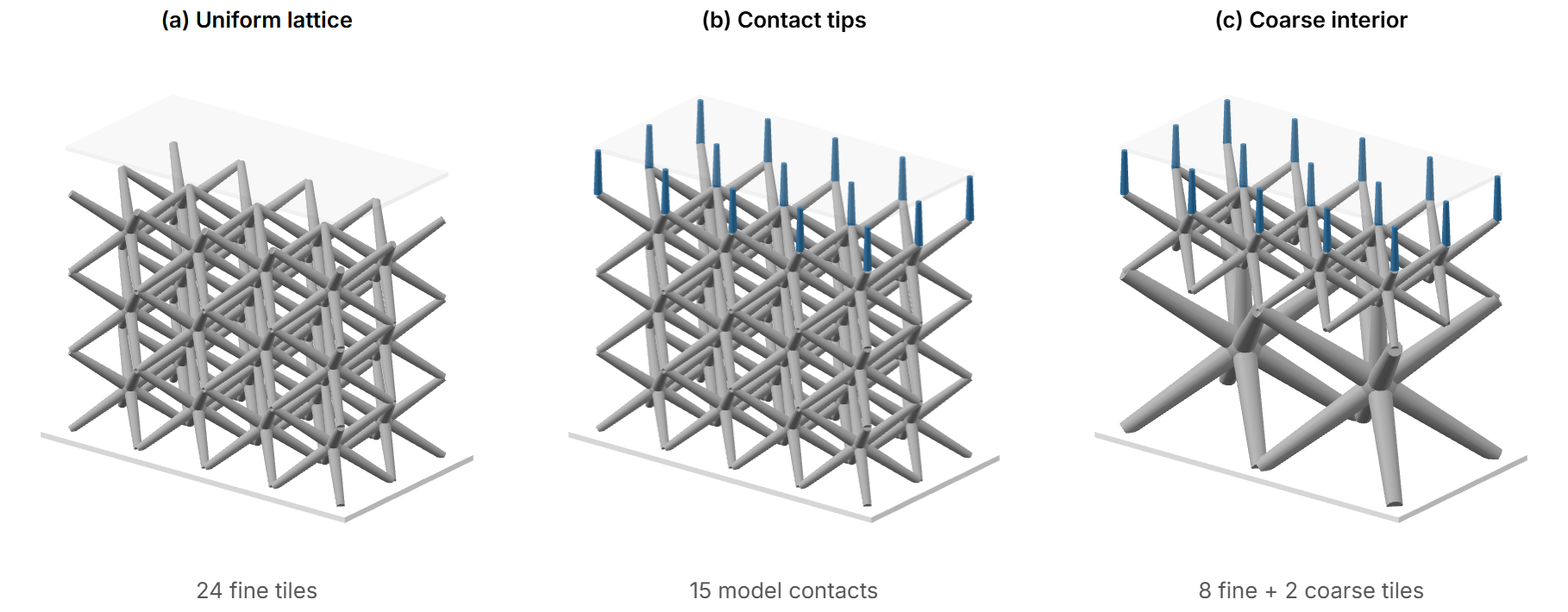
The multiresolution stage is a post-process on an already constructed support lattice. Tiles with tips directly attached to the model are preserved at the original fine resolution. Only tiles without such tips are candidates for merging, so this stage does not achieve a smaller structure by deleting the contacts that were just constructed.
At the first coarsening level, an eligible 2 × 2 × 2 block of fine tiles is replaced by one tile of twice the size. The construction requires all eight tiles in the block to have their complete diagonal-arm configuration and no directly supported tips. The same operation can then be applied recursively to blocks at the next level.
The resulting lattice can retain small tiles close to the model while using larger tiles in regions farther from direct contact. At a transition, the upward arms of a larger tile support arms from several smaller tiles above it. An additional vertical pillar can provide further support, and redundant downward arms in the neighboring tiles can be removed as part of the connection arrangement.
This is a constrained geometric simplification. The eligibility rules preserve a specific tile topology and the established tips; they do not merge every spatial block that happens to be empty of model geometry. The paper identifies relaxing these restrictions as a possible extension, rather than presenting unrestricted coarsening as part of the current method.
07 / Connect design parameters to analysis
The parameters influence different parts of the construction. Tile dimensions and allowable diagonal slopes determine the lattice layout. Tip diameter and maximum length constrain the model contacts. Base widening changes contact with the printing bed, while arm or central-joint thickness changes the material carried by the lattice itself. Treating these as separate choices makes it possible to change one aspect of the design without confusing it with another.
The volumetric spline representation provides a route to isogeometric analysis and to conventional finite-element models. The paper demonstrates analysis of support structures and examples of modifying geometry or thickness in response. Such a workflow makes the consequences of a geometric change inspectable under specified loads and boundary conditions.
A direct connection to analysis does not, by itself, make every generated support mechanically optimal. The paper reports analysis as a computational bottleneck and discusses fuller automatic lattice optimization and improved treatment of stress concentrations as further work. The appropriate assessment also depends on material properties, manufacturing constraints and the intended removal process.
Related papers
- Synthesis of lattice tiles using dualities of space filling polyhedraHong, Park, Asman, Rosenstock & Elber · Additive Manufacturing, 2026
- Conformal Parametric Microstructure Synthesis for Boundary RepresentationsHong, Park & Elber · Hyperseeing / SMI–SCULPT, 2022
- Multiresolution lattice-based support generation for additive manufacturingPark, Hong & Elber · Computer-Aided Design, 2024